
The Definitive Guide To Using Multimeters
How To Use A Multimeter
To use a multimeter, start by selecting the appropriate measurement mode (e.g., voltage, current, resistance) and range. Connect the probes to the circuit/component being measured, ensuring proper polarity. Read the displayed value on the multimeter’s screen, and if necessary, switch to a different range for more accurate results.
So, you’ve got a multimeter and now you’re wondering how to use it, right? Well, you’re in luck!
Using a multimeter effectively is an indispensable skill for anyone working with electrical and electronic systems. Whether troubleshooting a malfunctioning device or verifying circuit parameters, the accuracy and efficiency of your measurements hinge on your ability to operate this tool correctly.
This handy device can seem a bit perplexing at first glance, but once you get the hang of it, you’ll be testing, measuring, and diagnosing electrical issues like a pro. The good news is, the process of using a multimeter is quite simple.
In this post, we’ll delve into the nuances of multimeter operation, offering step-by-step guidance to ensure you get the most out of every reading. Let’s enhance your proficiency with this crucial instrument!
The Definitive Guide To Using Multimeters
This is the 13th article in our series, The Definitive Guide to Using Multimeters.
This article delves into how to properly use a multimeter, best practices for safety and some common errors while using a multimeter and how to avoid them.
In this article:
- The Process of Using a Multimeter
- Troubleshooting With a Multimeter
- Multimeter Safety
- Common Errors To Avoid While Using a Multimeter
- Multimeter Use FAQs
If you missed the start of the series: What Is a Multimeter?: The Definitive Guide to Multimeters, check it out now! You will be able to work your way back to this article quite quickly.
The Definitive Guide to Multimeters: Table of Contents
- What is a Multimeter?
- What is the History of the Multimeter?
- What Does a Multimeter Measure?
- What is an Analog Multimeter?
- What is a Digital Multimeter?
- Should I Use an Analog or Digital Multimeter?
- What is the Difference Between a Handheld and Benchtop Multimeter?
- What is a True-RMS Multimeter?
- What Features and Accessories Should I Look For in a Multimeter?
- How Accurate is Your Multimeter and Why Does it Matter?
- What Are Multimeter Ranges and Why Do They Matter?
- What Do I Consider When Buying a Multimeter?
- How Do I Use a Multimeter? – CURRENTLY READING
- How Do I Properly Maintain a Multimeter?
- How Do I Calibrate a Multimeter?
- What is the Future of Multimeters?
The Process Of Using A Multimeter
Using a multimeter involves a series of steps to accurately measure electrical parameters in circuits and components:
- Understand The Multimeter
- Select Appropriate Measurement Mode
- Select Appropriate Range
- Connect the Test Leads to the Multimeter
- Connect the Test Leads to the Circuit/Component
- Perform the Measurement
- Read and Record the Measurement Results
- Disconnect and Power Down
Let’s break down each of these steps in more detail.
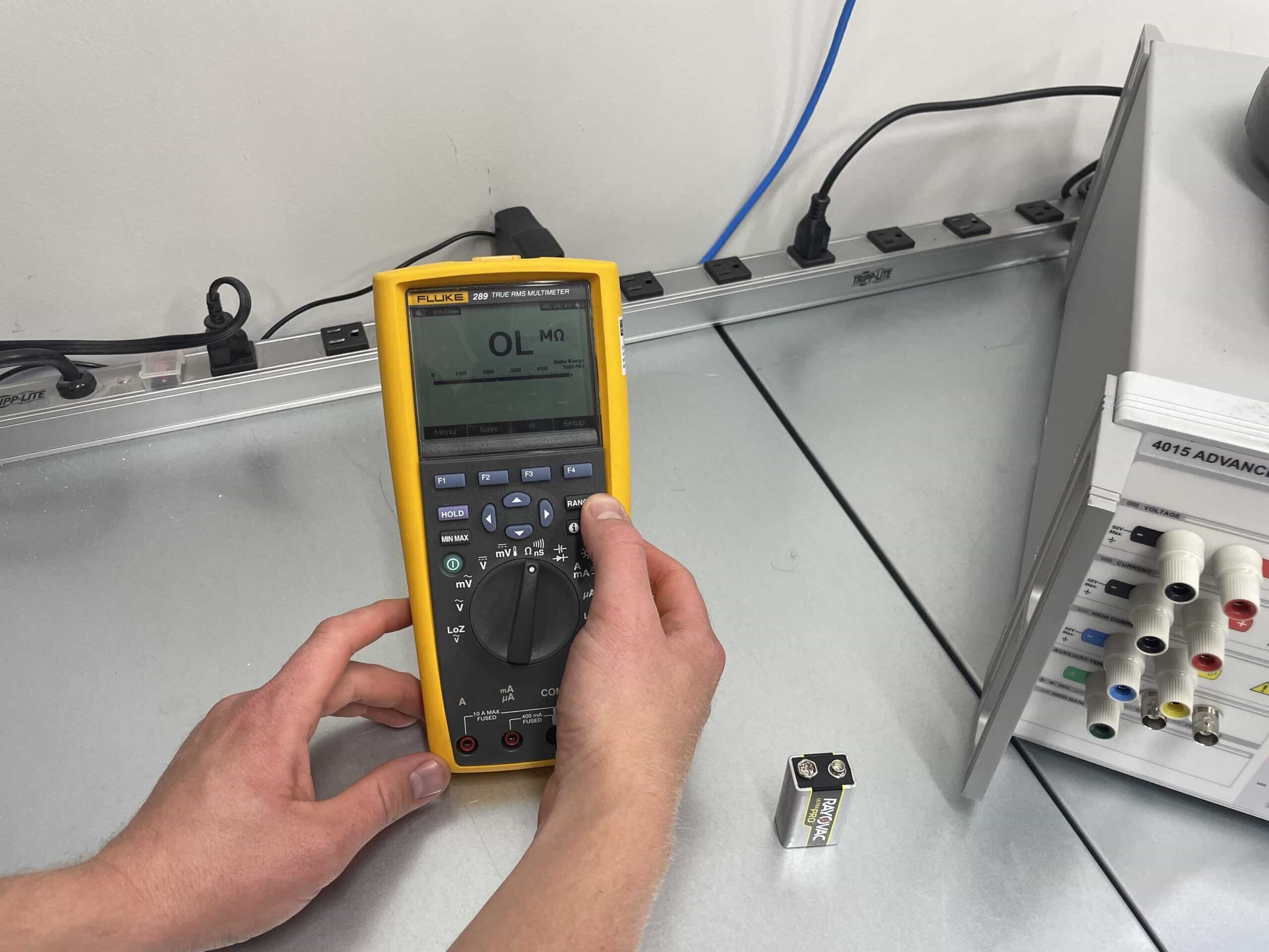
Step 1: Understand The Multimeter
If you have not used this particular multimeter before, start by familiarizing yourself with the different components of the multimeter, including the display, dials, ports, and test leads.
You will also want to check out the user manual for the multimeter. A lot of times, this can be found with a simple Google search.
Step 2: Select Appropriate Measurement Mode
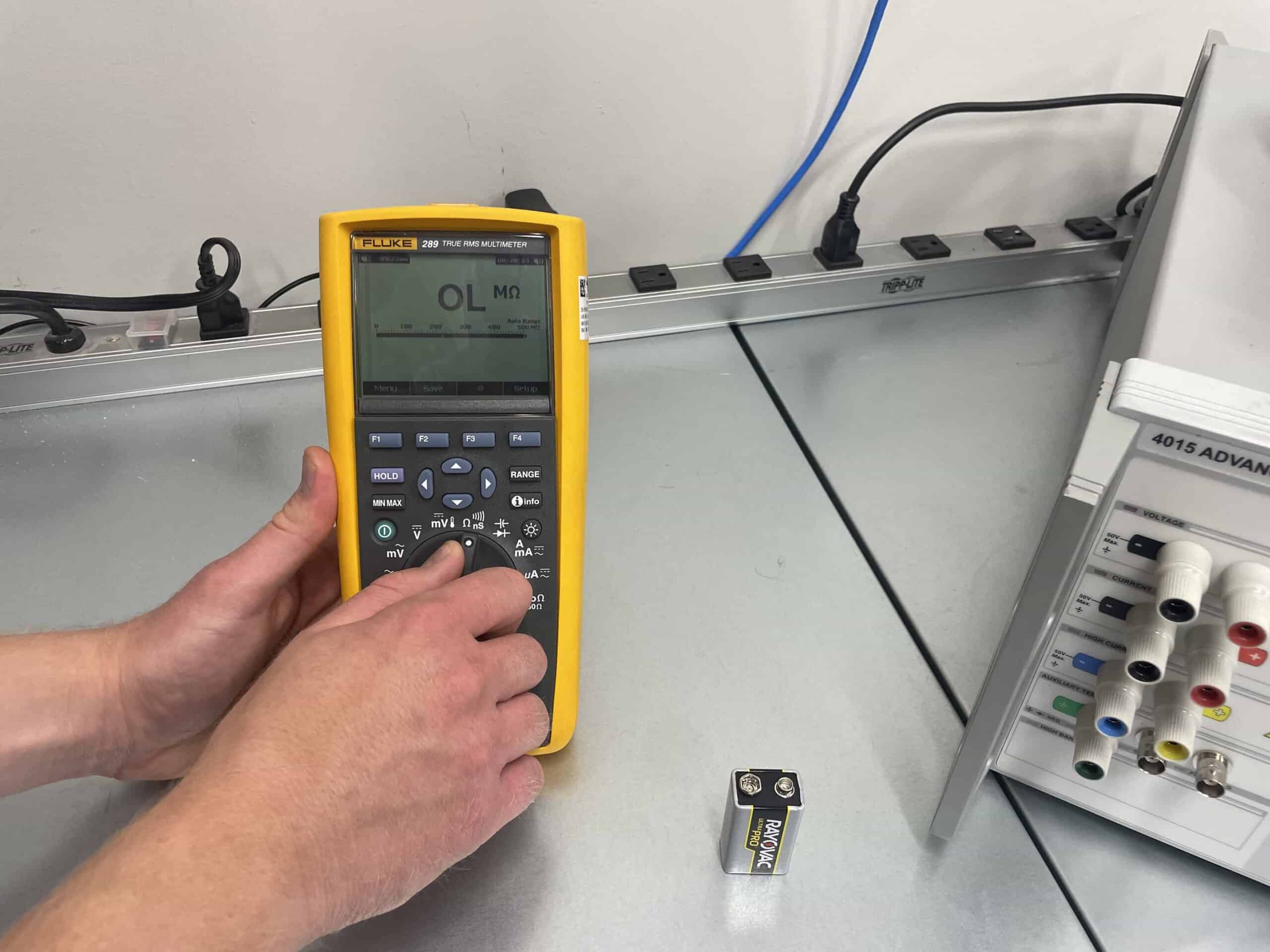
First, ensure the multimeter is in good working condition and set the dial to the appropriate measurement mode for your intended test, such as voltage, current, resistance, or continuity. Ensure the polarity is set correctly, if applicable.
Step 3: Select Appropriate Range
If necessary, select the appropriate range on the multimeter based on the expected value of the measurement. It’s generally better to start with a higher range and gradually decrease it for increased accuracy.
Step 4: Connect The Test Leads To The Multimeter
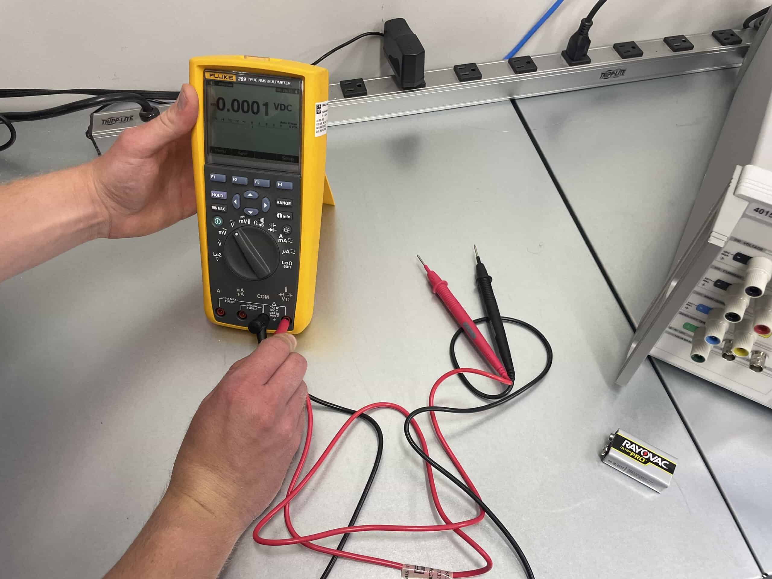
Next you will want to attach the red test lead to the multimeter’s red (or positive port) and the black test lead to the common (or ground port). Make sure the test leads are securely connected.
Step 5: Connect The Test Leads To The Circuit/Component
Depending on the type of measurement you’re performing, connect the test leads to the circuit or component you are inspecting accordingly. Avoid touching the metal tips of the probes when they are plugged into live circuits to prevent electric shocks. Additionally, make sure not to touch the tips together.
Step 6: Perform The Measurement
Each type of measurement requires its own unique process of completing the measurement:
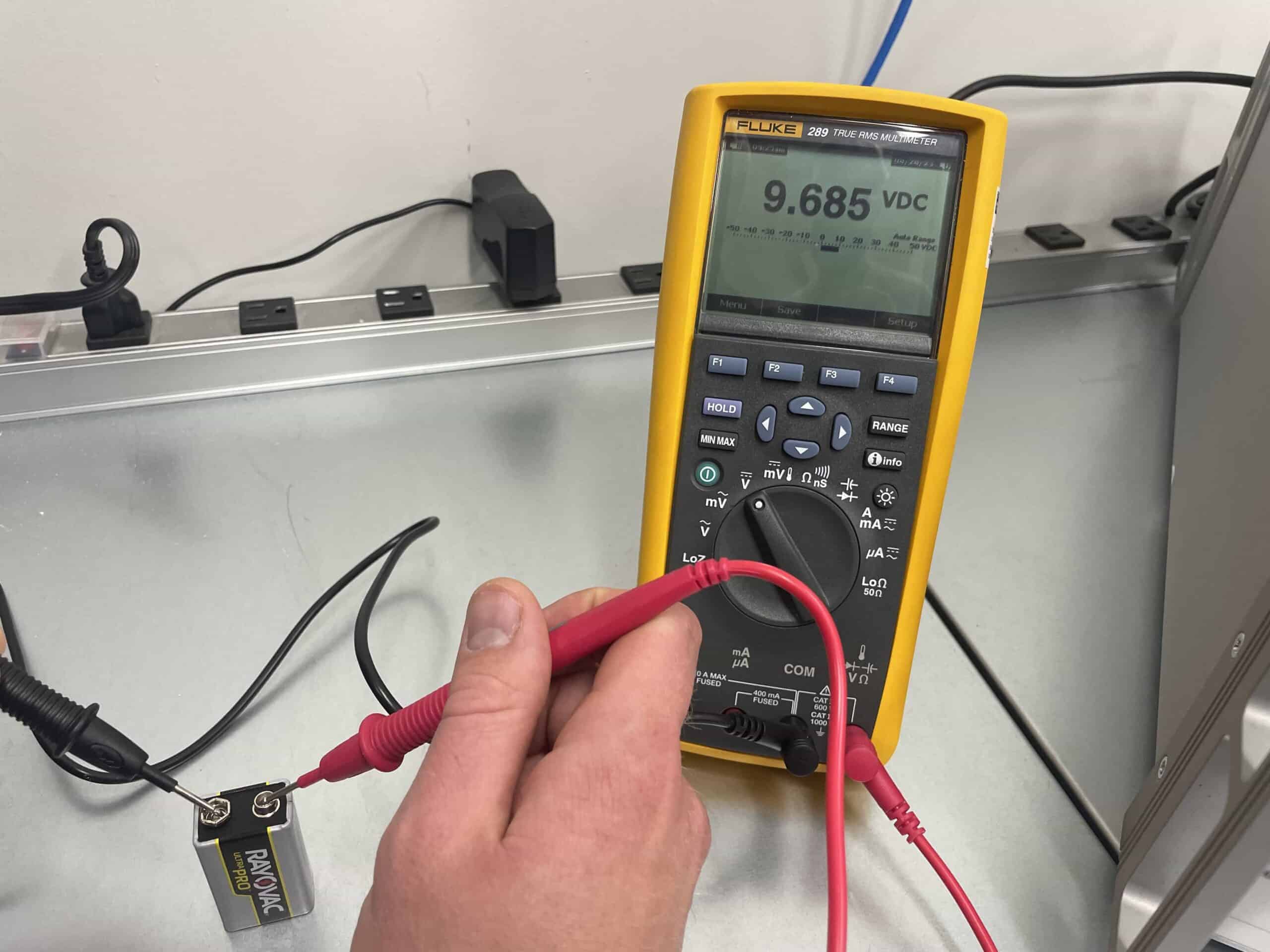
Step 6.1: How To Measure Voltage With A Multimeter
For voltage testing with a multimeter you simply need to place the test leads across the component or circuit you want to measure. You will want to squeeze the probes with a bit of pressure against the circuit, to ensure connection.
For example, if you were to use the multimeter to test the voltage of a battery, you simply need to touch the black probe to the ‘-‘ end of the battery (its ground) and the red probe to the “+” end (its power).
The battery example is an example of testing DC voltage. The process for measuring AC voltage with a multimeter is the same as measuring DC voltage, except that you need to have the multimeter set to the AC voltage setting.
Step 6.2: How To Measure Current With A Multimeter
To measure current with a multimeter, you will first want to break the circuit and connect the multimeter in series with the component. Then simply press the test leads to the component and hold firm to maintain proper polarity.
Step 6.3: How To Measure Resistance With A Multimeter
To measure resistance with a multimeter, you will first want to touch the tips of the probes together to ensure that there’s no residual resistance in the probe leads. The multimeter should read very close to zero ohms (Ω). This step calibrates the leads’ resistance so it can be subtracted from the actual measurement.
Next, touch the red probe to one end of the resistor or component and the black probe to the other end – just the same as you did for voltage measurements.
If the resistor is functioning properly, the resistance value on the meter’s display should be the same as the resistor’s rating. If not, the resistor is defective and needs to be replaced.
Step 6.4: How To Test For Continuity With A Multimeter
To check continuity with a multimeter, simply place the test leads across the component, just like you would for voltage and resistance.
When testing for continuity, if a complete path is detected, most newer multimeters will audibly beep. If your multimeter does not contain a function to audibly beep, the display should indicate a low resistance value, indicating continuity. If this does not happen, it indicates an open circuit (no connection).
Note: Similar to testing for resistance, you will want to touch the tips of the probes together to ensure that there’s continuity between them before starting the test.
Step 6.5: How To Check A Capacitor With A Multimeter
To measure capacitance with a multimeter, you will want to first remove the capacitor from the circuit. Be sure to do this safely, as capacitors can remain energized even after power is removed from the circuit. In order to do this safely, you can discharge the capacitor by connecting a resistor to it.
Once it is properly discharged, you can test the capacitance by placing the leads across the capacitor terminals. Touch the red probe to the positive terminal of the capacitor and the black probe to the negative terminal.
Step 6.6: How To Measure Frequency With A Multimeter
To test frequency of an electrical component or circuit with a multimeter, you will need to touch the red probe to the point where the signal is accessible (e.g., the signal generator’s output) and touch the black probe to the reference ground or common point.
There are two primary settings in which multimeters can measure frequency. Be sure to select the one most pertinent to your testing.
- Frequency Counter Mode: This is used to measure the frequency of an AC signal at a specific moment in time.
- MIN MAX Recording Mode: While connected to a circuit for a period of time, the multimeter will record the minimum and maximum frequency it measures during that time period.
Step 6.7: How To Measure Temperature With A Multimeter
If your multimeter contains the ability to measure temperature, you simply need to plug in the thermocouple adapter and measure the temperature of whatever you are inspecting.
Step 7: Read And Record The Measurement Results
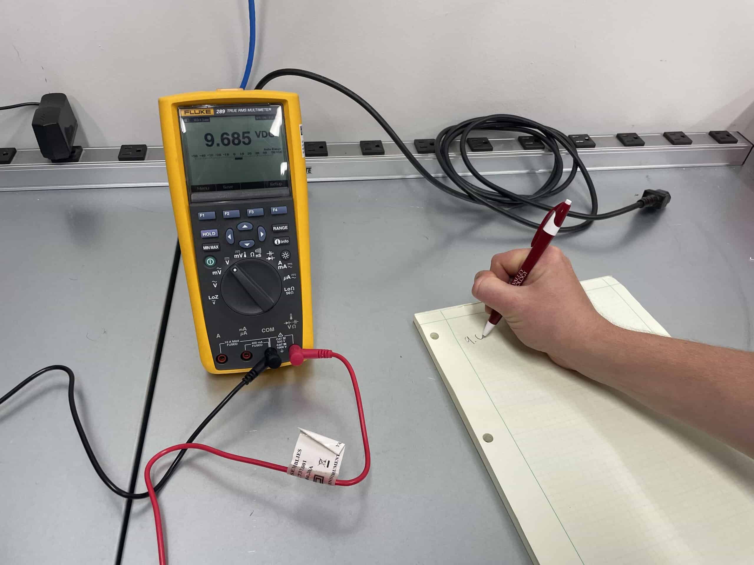
Once the test leads are properly connected, read the measurement displayed on the multimeter. Pay attention to the unit of measurement and the decimal point placement to interpret the value correctly. For analog multimeters, be sure to pay attention to the scale you are reading from.
Next, you will simply need to record the measurement. This can be as simple as a pen and paper or by utilizing a multimeter with data output to a computer or other device.
Repeat this process for any additional tests you need to complete on the circuit or component you are testing.
Step 8: Disconnect And Power Down
After taking the measurements you need, disconnect the test leads, return the multimeter to its default settings, and turn it off to conserve battery life.
If you had to disassemble the circuit you were testing, be sure to reassemble that circuit and reestablish power to it at this time.
It is important to note, that while these steps provide a general overview, it’s crucial to consult the specific instructions provided by the manufacturer for your multimeter model.
Troubleshooting With A Multimeter
In addition to the standard tests listed above, the multimeter is also an invaluable tool for troubleshooting electrical circuits and identifying faults. Here are some common troubleshooting scenarios where a multimeter can help:
- Testing an Outlet With a Multimeter
- Checking Power Supply Voltage of a Laptop
- Testing a Fuse For a Car’s Headlights
- Testing a Car Battery With a Multimeter
- Identifying a Short Circuit
- Verifying Component Values
- Testing Diodes
- Checking Grounding
Troubleshooting Scenario 1: Testing An Outlet With A Multimeter
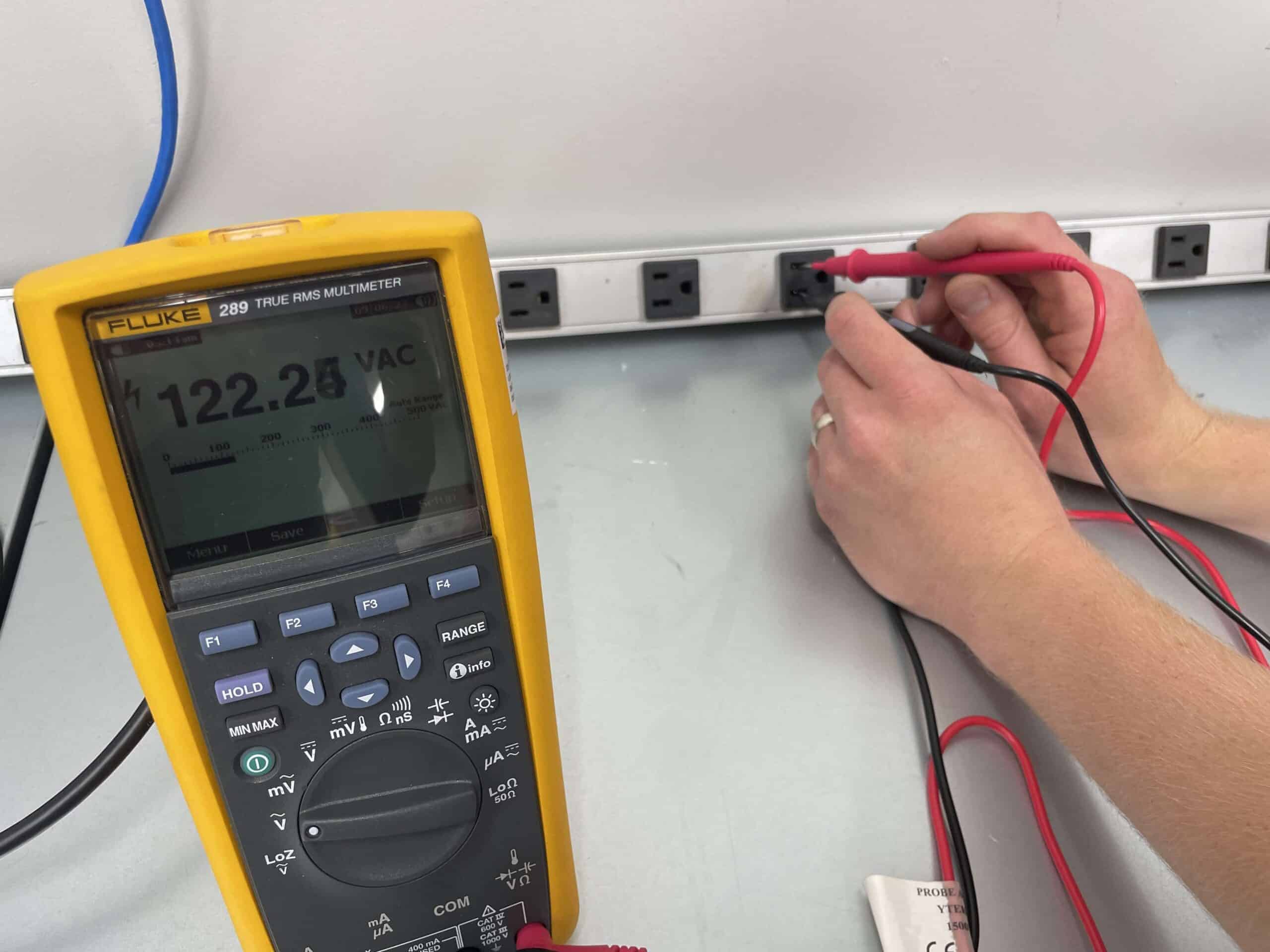
Let’s pretend you have a laptop that is not turning on. One of the first things you should check is whether the outlet you have it plugged into is actually supplying power. To test an outlet with a multimeter, insert the black probe into the smaller slot and the red probe into the larger slot of the outlet; a standard US outlet should read around 110-120 volts AC. If the reading deviates significantly, doesn’t provide a value or shows reverse polarity, you have an issue with your outlet.
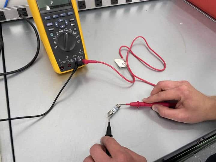
Troubleshooting Scenario 2: Checking Power Supply Voltage Of A Laptop
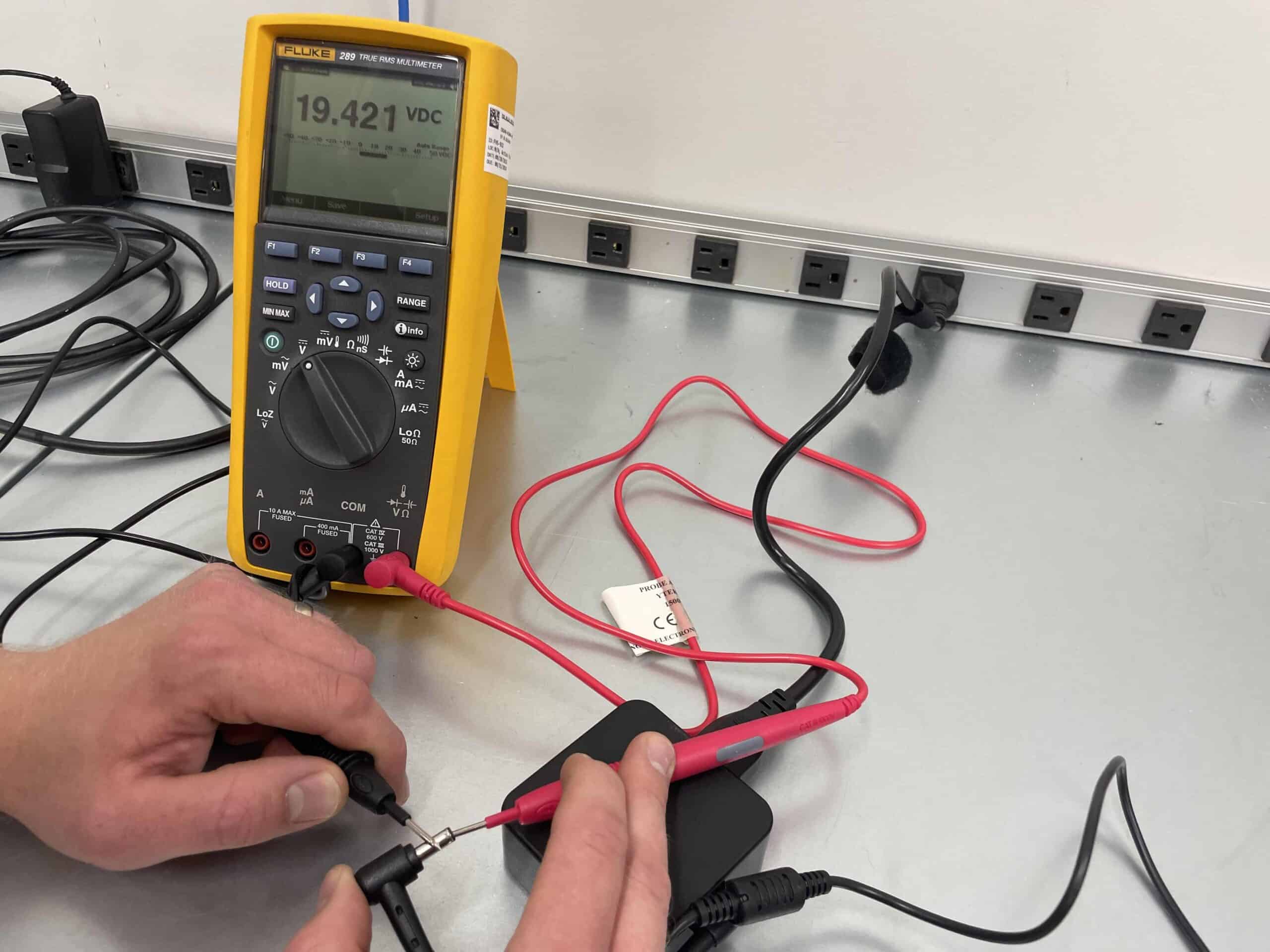
Let’s assume that your laptop still will not turn on. Now that we know the outlet is working properly, you suspect a faulty power adapter for the computer. Set your multimeter to DC voltage mode. Connect the red probe to the tip of the adapter plug and the black probe to its outer ring. Turn on the adapter and read the displayed voltage. If it’s significantly lower than the rated voltage, the adapter might be the issue.
Troubleshooting Scenario 3: Testing A Fuse For A Car’s Headlights
Your car’s headlights are not working. There is a decent chance it is the headlight fuse that working poorly. To check the headlight fuse, set the multimeter to continuity mode. Remove the headlight fuse and touch the probes to its terminals. If the multimeter beeps, the fuse is fine. If it doesn’t beep, the fuse might be blown and needs replacement.
Troubleshooting Scenario 4: Testing A Car Battery With A Multimeter
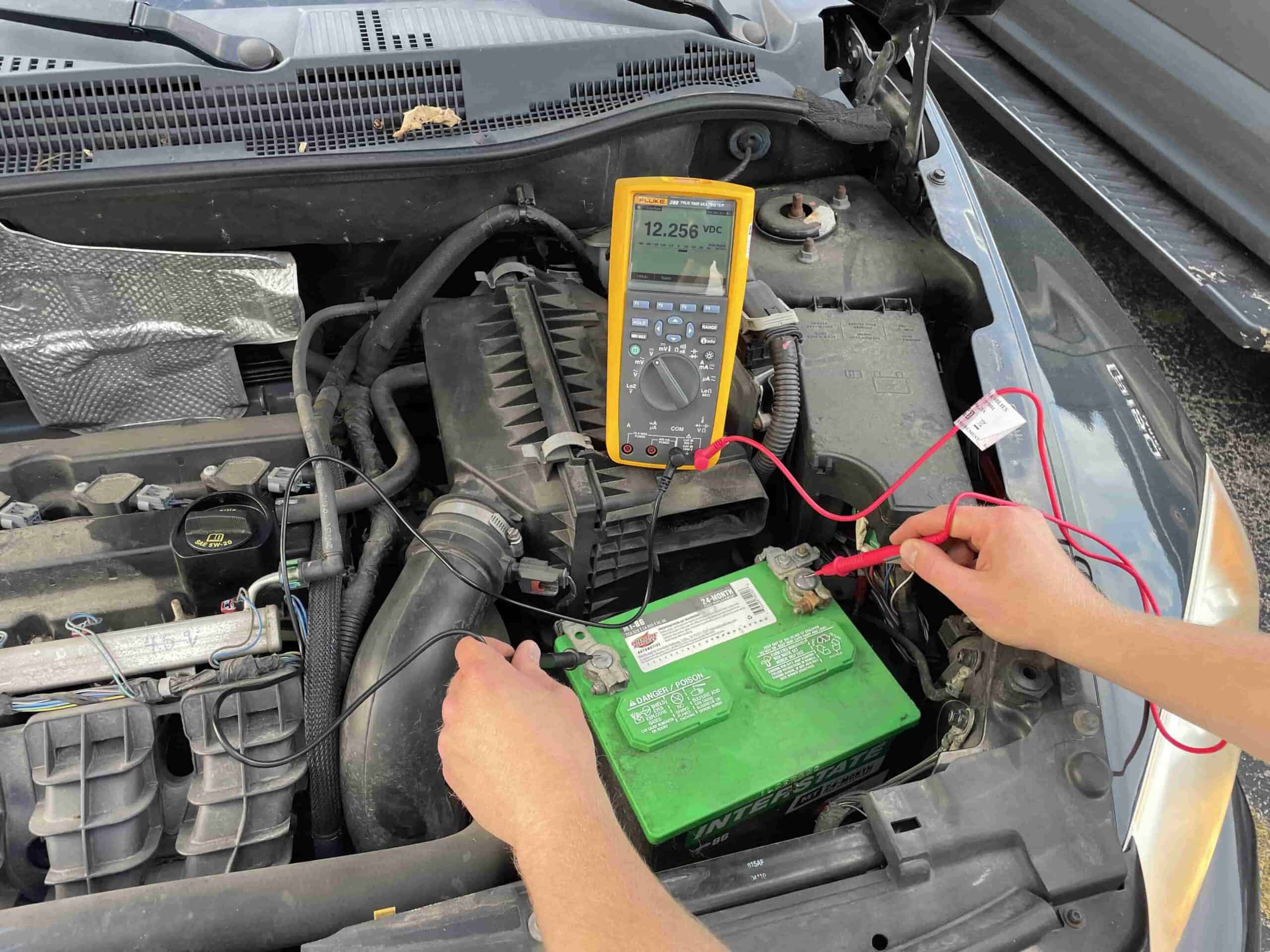
Your car won’t start. In fact, the engine won’t even turn over. We have all been there. The most likely culprit is your battery is dead. To test this, take out your multimeter and connect the red probe to the battery’s positive terminal and the black probe to the negative terminal; a fully charged car battery should read around 12.6 volts DC. If the reading is below 12 volts, the battery may be discharged or faulty.
Troubleshooting Scenario 5: Identifying A Short Circuit
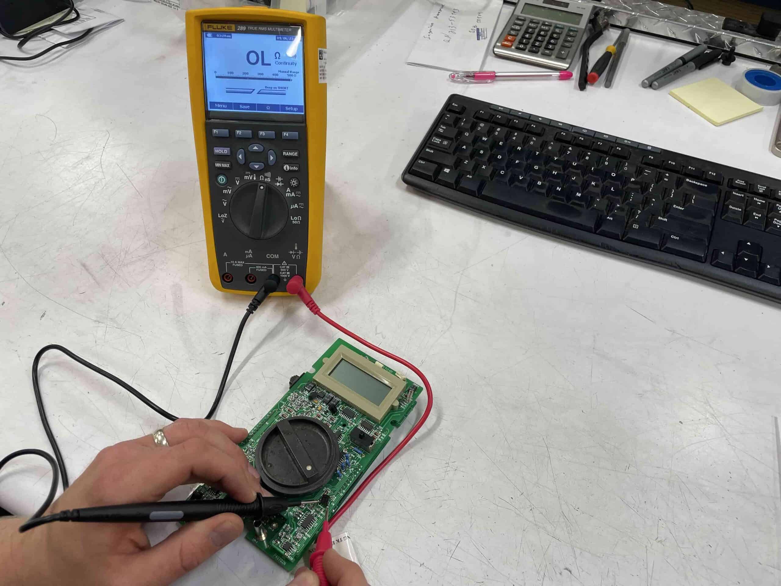
You’re troubleshooting a circuit board with erratic behavior. Set the multimeter to continuity mode and disconnect suspected components or wires. Touch one probe to one end of the disconnected section and the other probe to the opposite end. If the multimeter beeps, there’s a short circuit causing the issues.
Troubleshooting Scenario 6: Verifying Component Values
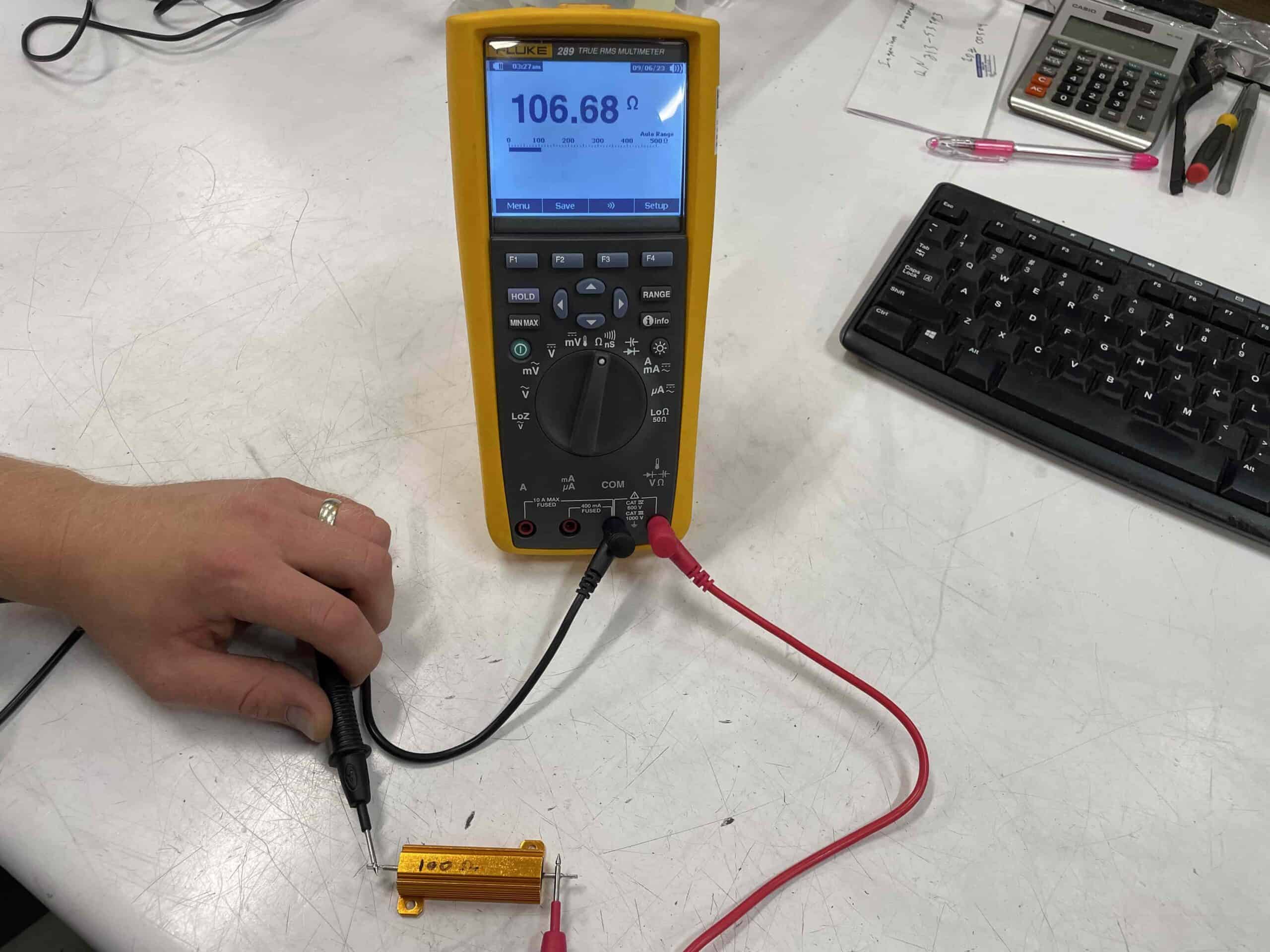
You’re repairing an audio amplifier and suspect a faulty resistor. Set the multimeter to resistance mode. Measure the resistance of the suspected resistor and compare it to the expected value. If it’s far off, the resistor might need replacement.